Week 8 Entry - Rasterization Pipeline & WebGL
Rasterization Pipeline
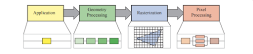
In contrast to the previous rendering method we've implemented, being the raytracer, rasterization works in essential the opposite direction of computation for the final pixel colors displayed on the screen. Raytracing works through the concept of being image-centric; rays are cast from the location of each pixel (relative to the camera behind it) and information is gathered relative to each object which that ray, or subsequently cast rays, comes into contact with. Rasterization operates within the constraints of an object-centric rendering environment. This methodology follows each object within the screen through a process of transforming to screen coordinates, examining each pixel the object is within, and determining if it's the closest object within each given pixel. Pixels are then shaded given this object is the new closest within that position of screen space and the old shading information is thrown out (for our simple, opaque objects implementation).
WebGL
For the implementation of our rasterization pipeline, we are utilizing a graphics language so that we may leverage the processing power of our graphics processing unit to compute the shader data in a parallel, brute-force manner. WebGL, a JavaScript API, will allow us to run our code within a browser and have a rendering environment (hardware accelerated) run within a canvas element provided through HTML. Our implementation will be mostly centered around allocating appropriate geometry and matrix information to GL buffers for the GPU to use in computations and using a basic implementation of both the vertex and fragment shaders. The program we've created, rendering a line grid and a single triangle, feels very introductory and would not natively be capable of generating multiple triangles without altering some functionality. That said, however, the simplicity of the implementation was helpful as the overall code structure was unexpectedly complex and was not easy to follow without spending time scrolling through some manual pages.
Debugging & Translation to the Actual Code
Before diving into the struggles below, I will say that the whole process of utilizing a graphics API was very interesting as it made some previously seen content on game development less magical and easier to follow (there's still a slight vibe of black magic going on). Until working on this project, I was otherwise lost and mentally checked out when Sebastian Lague or Yan Chernikov (The Cherno) would even begin talking about shaders as I just didn't even understand where the code was running let alone how it was influencing the final imaging. While I am still a little lost on how the implementation directly follows the rasterization pipeline on a stage-by-stage stepping (especially with the parallelism used on the GPU side) this homework made me more comfortable to perhaps write my own implementation from scratch so that I may have a better understanding of why and how each step of code is done.
Prior to attempting to start the next week's rasterization project, I will undoubtedly need to download a debugging extension to help with the WebGL side of the code. I had seen the video provided on one debugger method from the week's modules but got so lost in trying to best understand the code provided that I hadn't remembered to return and add that in. There were two particular points of confusion that kept me from working forward at points during the completion of this assignment:
(1) Formatting the linePositions.push() arguments
Having the triangle as the only implemented point of reference for how the buffers should be filled, I spent a fair portion of my time on the assignment trying to properly fill the array created for the lineGridGeometry's vertexes. Not knowing, at the time, how the final array was to be structured (as either an array with only the individual float elements, not separated by object OR an array of nested arrays with those nested arrays each containing the elements for a given line's vertexes), I eventually ended with the following:
 |
| Each element of the array (to be cast as FloatArray -> buffer) represents one of three variables used by the shaders for the appropriate number of vertexes. In this case, the geometry is that of a line, so every two triplets of variables will be used to represent the start and end points of that line between which the program will interpolate. |
(2) Applying the translation -> rotation matrices to the triangle
Now this one threw me for a loop...I also found that my partner ran into the exact same situation later when their implementation reached the same point. When applying the rotation and translation matrices to the triangle world matrix, I initially applied them on separate lines, with the translation being applied after the rotation. The reason for this was I wanted the rotation to occur (with the degree of rotation relative to a changing variable of time) on the object's model space, and I then wanted that rotated object to be translated to a given point in front of the camera, within the screen space. The result of my initial process above was a translated but not-rotating triangle being rendered. The solution I used after was applying the matrices on one line, with right -> left matrix logic being followed. With this logic, however, I still felt that my initial implementation would have functioned in the same way...

Having dug into it a little, at least as far as I understand, the factor keeping my initial method from functioning correctly is the makeTranslation(x,y,z) function altering the calling matrix by changing it to an identity matrix before changing the w vector4 values. Commenting that line off of the function does allow the first attempt I made to work as well as the one I ended up settling on.
Questions: does the below implementation apply the rotation after the translation? If so, why does it still appear to rotate the triangle and then translate it (the triangle is not rotating around the scene, but instead it is rotating within its y-axis as it should be)? In my head, the triangle would instead be rotating about the scene's origin at a radius of 7 with this implementation.


Comments
Post a Comment